Head Mounted Scope
Contents
Overview
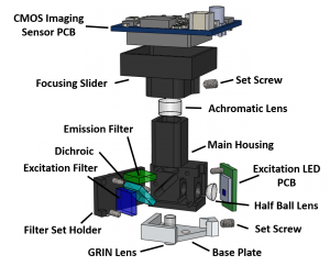
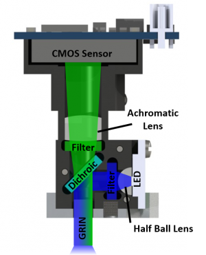
The head mounted scope consists of a machined Delrin housing, optical filters and lenses, an excitation light source, and CMOS imaging sensor. The mass of the system in under 3 grams and connected to the DAQ hardware using a single coaxial cable. The body and optical components can be easily hand assembled using only forceps and a torx T2 driver. Optical filters are slide in from the side of the scope and held in place with a filter cover plate. The excitation half sphere lens sits in a spherical cutout and held in place by pressure from the LED PCB (optical glue is optional). The achromatic lens is slid through the top emission hole and either press fit into place or optical glued.
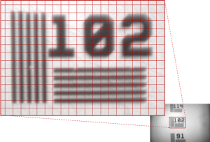
Adjustment of focal plane is achieved through adjusting the distance between the CMOS imaging sensor and other optical elements. The CMOS imaging sensor is mounted onto a sliding focusing mechanism which is moved by hand and locked in place with a 00-80 setscrew. Roughly speaking, movement of about 5mm of the CMOS imaging sensor results in a focal plane change of ~150um.
The scope attaches to the head of the animal with the use of a small aluminum baseplate. The baseplate and scope have a matching set of 3 rare-earth magnets which helps with mounting the scope on an awake animal. Once the scope is in place a 00-80 set screw is used to fix it in place.


